Showing posts with label led light. Show all posts

Tuesday, October 20, 2015

License Plate Led Lamp DIY

Led due to their low current consumption characteristic are nowadays being used on motorcycles and automotive lighting solutions. They are replacing those filament bulbs for signal lights, brake and tail lights, panel lights, plate number led lamp and as well as daytime running lights. In this page, I am trying to make my own led lamp  for license plate for i broke the housing when i've gotten to replace those busted bulb, so i have no choice but to replace them with led light type and mold the board that will fit inside the broken housing.

License plate light housing is removed taking it apart to look for where the smd led array will fit.
The broken hole to where the light bulb holder cannot be fixed and will no longer hold it in place. The holder broke due to the brittleness made by the bulb heat during operation was the most likely suspect. Damn bulbs.. :))

Taking it apart, There's the area that can be used to hold the board of the led.
Cut an empty copper board that will fit on that area and come up with this.

note: The process of how to make PCB on all my projects here are not being used here. If you want to know how to make one, then probably your best tutorial is....GOOGLE :)

Moving forward

After removing excess copper board to produce the PCB for the SMD led. In order for the foil path not getting corroded by moisture, i have no intentions of removing those toner coating. Only the area for soldering will be scrape.

Now populate the board with the parts needed for this DIY. Smd led first, look for proper orientation. They are 3 in series with each string have their own limiting resistor of 180 ohms, then paralleled those strings or array.

(no schematic is needed if you know how to work on light emitting diode)

SMD led where taken from old household led lamp,  just recycled every part i have.

After populating the board. Fit it inside the license plate lighting module as shown using the white holder to secure the led array inside.

Testing it is easy, use 12 volts supply. There let there be a plate number led lamp.

By comparing the led lamp to the bulb type..What a big difference with the intensity of the light. Successful DIY.


Read more »

Driving COB Led

COB, (Chips on Board) , multi LED (light emitting diode)chips are packaged together as one lighting module. When it light up, it looks like a lighting panel. COB LED is multi chips packaged, it can 10 times more increase lighting area,so it avoid uncomfortable glare by the maximum extent.By now, for small size chip, some famous LED chip manufacturer can reach 249lm/watt @ 20mA. But big size LED chip can only reach 161lm/watt @350mA.The light efficacy decrease when chip size is bigger. Also when LED driver increase current to LED, the light efficacy per watt is even low.COB technology provides significant advantages over surface mount technology (SMT) components in the design with better temperature management, smaller size of lumen packages and lower production costs. In general the life span of COB LED can be 40000-50000 hours.

COB led as shown above compose of seven (7) led in series and requires again a constant current driver, from tha specification found all over the net requires 12v driving them at 300mah of current.From the previous page that can be found here PROJECT LED HEADLIGHT . I still use the same DIY led driver so that the voltage of the led in series will float depending on the forward voltage of each led and the current to the led will then remain constant.
Actually, there are so many led driver being offered all over the net, i myself  wanted to have one of them at least, but due to lack of resources, i just make my own out from those datasheet of every semiconductor that performs the same function for led lighting. And from the schematic, will make PCB for those components to make the circuit work. Pre testing is required not to waste every component.


Schematic of the led driver can be found here led boost constant current driver . For Pcb, you really have to make it on your own since i am just making mine using pen. But to make it easier, there are lots of downloadable PCB software available for all of you to test.

COB led connected to the led current driver (sorry for the photo, grayscale color :(


Beam shot was taken at a 90 degrees, note that the surrounding do not have any other lights on, only the COB led itself..hmmm too powerful for me, wide beam actually cover lots of area than my previous attempt using seven (7) x 3 watts power led in series.


Shot taken now at 45 degree from the actual beamshot, too much glare is obvious, (disclaimer), when doing such experiments on high power leds, avoid prolong exposure of the eye to the actual beam, you may temporary have a blur vision after, and may cause eye disorder.


Actual beamshot towards the floor at my garage, very interesting that due to the wide cover area of the led the beamshot was as if i am using a CCFL energy saving lamp, so that is why manufacturers use it for household lighting. :)


Read more »

Digital Tachometer

This is my digital tachometer i made a long time ago on my suzuki shogun 125cc and still in active up to date. The tachometer incorporates a programmable shift lights, the red line can be programmed depends on where to shift at a certified RPM...watch the video to see it in action.


Read more »

Motorcycle Led Headlight

This page an update to my previous post Project LED headlight to where i incorporate it already to my sinski 150cc headlight housing. (actual BEAM shot on road not yet taken)

The photo shown with a beam shot taken at an angle of 45 degree in front.
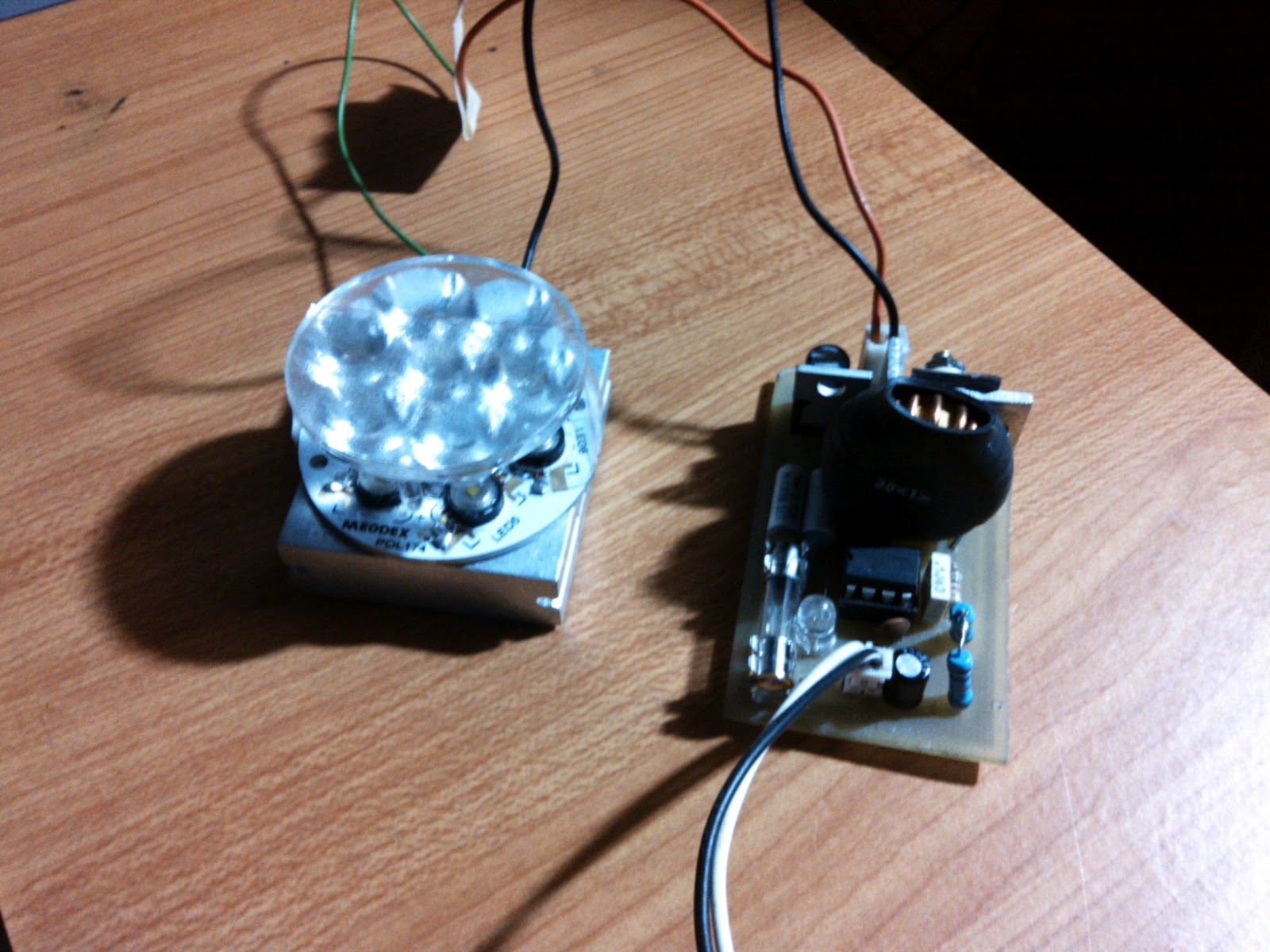


Constant current led driver is needed to prolong the life of the led array and to compensate for the changes in input voltage during use.


The headlight housing to where i'll be incorporating this led headlight prototype to replace my scooter filament type headlight. The original uses 35watts for low beam and 35 watts for high beam.


Headlight lens need to be removed in order for me to fit the led headlight collimating lens. The cover of the headlight was easy to dismantle..(note that new or brand new housing is not that easy to remove because of the anti moist glue.) my headlight perhaps due to the long period it was stock, the glue just didnt stick that much, and dis assembly was a snap.


With the original bulb remove, the hole to where my led headlight bare board, is actually fit, like pair made for each other..:-)) and no more additional drilling holes for this project.


Perfect fit without the collimating lens.


with collimating lens attached on the led array to focus the beam in front.


view of the heatsink for the bare board of the led array. Heatsink is needed, (fan not necessary when the bike is moving, rushing air in front will cool down the heatsink..


And its time to power up the led headlight to see how it went well. I used for this test 12 volts 1.5 ampere wall adapter.


Read more »

Inside E27 5 Watts Led

I know many of you wondering what's inside a household led lighting such as this one shown on the photo. A 5 watts led light with E27 type socket, same as those CCFL energy saving lamp. They are commonly been found nationwide on hardware store, supermarket and electronic supplies at an affordable price. Being an enthusiast and a DIY'er, i got curious again what was inside this kind of household lighting. I recently bought one for another experimentation and wanted to take a peek inside.


By twisting the diffuser, at last the leds came out and i wasn't surprised at all. 5 pieces of 1 watt led was used to bring out the 5 watts specification of this led lighting. They were soldered on an aluminum piece of PCB, to where they will act as the minimum heatsink, and the violet (purple) fins as the main thermal support for the assembly. Getting deeper onto it, i desoldered the board to the main heatsink and


Read more »

Side mirror signal lights part III

Here are the step by step..(partial) on how to make your imitation KOSO side mirror as signal lights.

First gather all the materials i posted on this part 1 signal side mirror.


 The picture at the right is the NOT moded Koso side mirror.


And after hours of drilling, sanding, and cutting,

the back of the side mirror will look like the one on the right photo.The acrylic cut sheet will perfectly fit as if it was not there.


Read more »