Showing posts with label custom led lights. Show all posts
Showing posts with label custom led lights. Show all posts
Tuesday, October 20, 2015
Led Tail/Brake Light Evolve

Filament bulb tail brake light bulb often failed due to the vibration at the back of any motorcycle, and it is un noticeable by the rider up until they are warned that they do not have a brake light to alert motorist at the back that you are stopping. I was once caught with a busted rear end light, thus this keeps me think of "Why not replace it with LED bulbs instead of filament bulb". In this way, i can conserve battery power, more reactive light at the rear when stopping, Yes led reacts faster than filament bulbs.
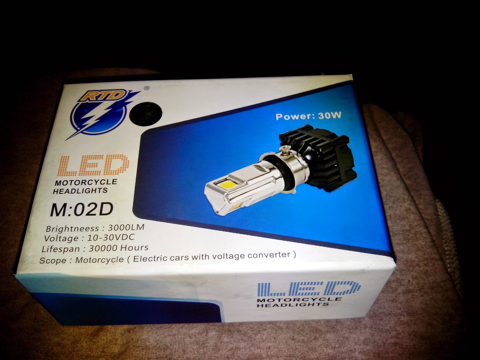
Motorcycle Led Headlight

The photo shown with a beam shot taken at an angle of 45 degree in front.


And its time to power up the led headlight to see how it went well. I used for this test 12 volts 1.5 ampere wall adapter.


Yamaha Mio Soul Led Headlight Conversion
How to install RTD triled on a Yamaha MIO SOUL properly? Very easy actually, but readers must be advised that to power the Led, DC must be used, unfortunately, almost all motorcycle and scooters original headlights are powered by AC being supplied by the stators. When you switch ON your headlight as the engine is running and the bulbs and panel lights are fluctuating, then automatically, It is AC powered and have to be converted first to DC before installing Led Headlights.

When done.

 |
| Original DUST cap |

look for any sort of plastic cap of the same size of the original but with more height, in my case, I use the cap of a choke/carburetor cleaner that fits perfectly with same outer diameter as the original and when it was placed to cover the RTD triled.

Wiring is not that difficult too, since the system was already converted to DC headlight. follow the instruction of the three wire to which is which,
Mio soul color code for the headlights are this
1. Green wire --low beam
2. Yellow wire --high beam
3. Black --ground
The approach is not to cut any wires to preserve the original wiring in case problem arises with the led replacement and always ready for the refitting of the original bulb headlight.

 |
| View of RTD triled inside the reflector |


 |
| low beam |
 |
| Hi beam |
Integrated TAIL/Brake, signal lights
Ever seen a ford expedition with just a full REAR red lights where a signal, tail and brake lights are done by those RED lights. They are called INTEGRATED rear lights and can be done on motorcycles too. Take a look at the video. This was the very first version of my diy works with my bike a long time ago, to where my signal lights tail lights and brake lights are compose with just an array of led at the rear.
Circuit:

I used this circuit posted led-brake-light This will be your TAIL/BRAKE light controller, it needs two of this for left and right led array assembly. to incorporate the SIGNAL lights on this circuit, we have to use two 12 volts miniature relay.
 two of this single pole single throw relay will be used to switched the negative line of the led array on the circuit above. The NC or normally closed pins will be used. Look at the modified schematic below.
 Cut the negative path of the led array from the driving mosfet and wired it to the normally closed pins of the relay so that when powered on the path of that negative pin of the array is still connected. And when you turn on the signal lights, the relay will be activated thus cutting the line of the led array producing a flashing effect on your integrated rear lights. This circuit by the way will be on all the time, that when you on the ignition switch, your tail light must be on so that the rear signal lights function during day time.
Part list:
D1-D2= 1n4007
ZD1= 15volts /1watt
ZD2= 9-14 volts / 500mw
L1=22uh
C1=15uf/35v
R1 / R4= 10k ohms
R2 = 1.3 ohms
R3 = 16.1 ohms
R5 = 2.2k ohms
VT1 = 2n3904
VT2 / VT3 = mtp3055e (mosfet)
for signal lights add on
RL1 / RL2 = 12 volts miniature pcb relay
Read more »
Circuit:

I used this circuit posted led-brake-light This will be your TAIL/BRAKE light controller, it needs two of this for left and right led array assembly. to incorporate the SIGNAL lights on this circuit, we have to use two 12 volts miniature relay.


Part list:
D1-D2= 1n4007
ZD1= 15volts /1watt
ZD2= 9-14 volts / 500mw
L1=22uh
C1=15uf/35v
R1 / R4= 10k ohms
R2 = 1.3 ohms
R3 = 16.1 ohms
R5 = 2.2k ohms
VT1 = 2n3904
VT2 / VT3 = mtp3055e (mosfet)
for signal lights add on
RL1 / RL2 = 12 volts miniature pcb relay
Led ANGEL EYES (custom built)

ACRYLIC rod is very difficult to find at local store, only sheets are. But do you know that those so called VENETIAN BLINDS that some houses use to their windows to block the sun have this kind of rod. :-)

For the materials and tools that we will be needing to perform this DIY are
1. The rod of course
2. heating element, (HEAT GUN, hot air gun or station) note: do not use any flames on the rod or it will produce bubbles inside that will ruin the rod when lighted
3. Led 2 pcs color of your desire
4 shrinkable tube--more on this later
5. soldering iron and lead
6. pieces of long wire for the leds
7. 2 pcs 1 kohm resistor--to limit the current on the leds when 12 volts is used
8. mini drill to put holes and rings around the rod
9. cutting disc, drill bits, or any means that can put holes at each edge of the formed rod--later on this one


Another shot of the bubbles, (need to sand it later)


not as flashy like the CCFL type angel eyes but worth a try.
Subscribe to:
Comments (Atom)