Showing posts with label led. Show all posts
Showing posts with label led. Show all posts
Tuesday, October 20, 2015
Side mirror signal lights
--> just an update to my post signaling side mirror, now as well as the face of the side mirror..heres the link for PART 1
it is noticeable that it aint that bright since theres an issue if i'll make it as bright as it should be and might implict the visibility of the face of the mirror..so i intentionally make it like this..that during daytime all you can notice is just some dots on the edge of the mirror..as shown

Read more »
it is noticeable that it aint that bright since theres an issue if i'll make it as bright as it should be and might implict the visibility of the face of the mirror..so i intentionally make it like this..that during daytime all you can notice is just some dots on the edge of the mirror..as shown


Driving High Power Leds
A 1 watt high power leds in my opinion needs at least a 350mah constant current driver to produce its total luminance, whereas a 3 watts needs 700mah, a 5 watts needs a 1A driving current and so on and so forth.
In the picture above, is a 3 watts X 3 watts high power leds made by SEOUL semicon model P4 i ordered online. It been driven at a selectable switch in a 350mah and 700mah constant current configuration, using a switching mode type circuit. Commonly known circuit that can be used are, NCP3063 by ON semiconductor
LM3404 by national , the cheaper MC34063 by motorola...etc etc.
sample circuit as shown here:

Led Brake Light

Driving COB Led

COB led as shown above compose of seven (7) led in series and requires again a constant current driver, from tha specification found all over the net requires 12v driving them at 300mah of current.From the previous page that can be found here PROJECT LED HEADLIGHT . I still use the same DIY led driver so that the voltage of the led in series will float depending on the forward voltage of each led and the current to the led will then remain constant.

Schematic of the led driver can be found here led boost constant current driver . For Pcb, you really have to make it on your own since i am just making mine using pen. But to make it easier, there are lots of downloadable PCB software available for all of you to test.


Wireless Helmet Stoplight


Zeus 508w Visor Light

This is my helmet, as you can see the outer edges of the visor emmits blue light without having the entire visor, the visibility was not affected unless your visor have scratches and dents, that the light will penetrate too. Some people think its kind a dangerous to put light that will affect visibilty, but this mode does not as lights will not be focus directly to your eyes unless you concentrate looking at it instead of focusing on the roads.
 This mods takes a little time to assemble and make.
You just need
- two cellphone supebright leds,
- a length of enamel wire at least number 26AWG, and or any unused earphone wire thats enameled coated.
- a li-ion battery preferably 4 volts,
- a push button tact switch and
- a know how to solder.
LED lights
Led lighting solution for motorcycle are the trends of enthusiast from filament bulbs of their signal lights thus improving night time visibility and faster response of LED including signal lights, tail lights and brake lights, soon even headlights will be led..THIS is light emitting diode era anyway.
 My DIY led amber signal lights.
 All you need is a PCB board, couple of leds, resistor of 470ohms for the three in series, a wedge type holder, a small signal diode 1n4148 for reverse polarity protection..and a solder know how technique.


this is how it lights offset from the camera to see the effect.
Read more »


this is how it lights offset from the camera to see the effect.
Digital Tachometer
This is my digital tachometer i made a long time ago on my suzuki shogun 125cc and still in active up to date. The tachometer incorporates a programmable shift lights, the red line can be programmed depends on where to shift at a certified RPM...watch the video to see it in action.
Read more »
LED Signal Light Bar End (how to make)

Many article posted here actually have photos and videos showing my bar end at work, and many of you are thinking how to make one, well sorry for the late responses. This article and post will show at least an idea on how to produce your own glowing bar end lights.


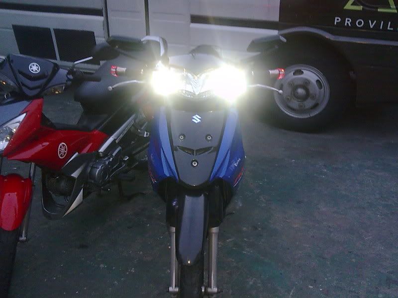
Motorcycle Led Headlight

The photo shown with a beam shot taken at an angle of 45 degree in front.
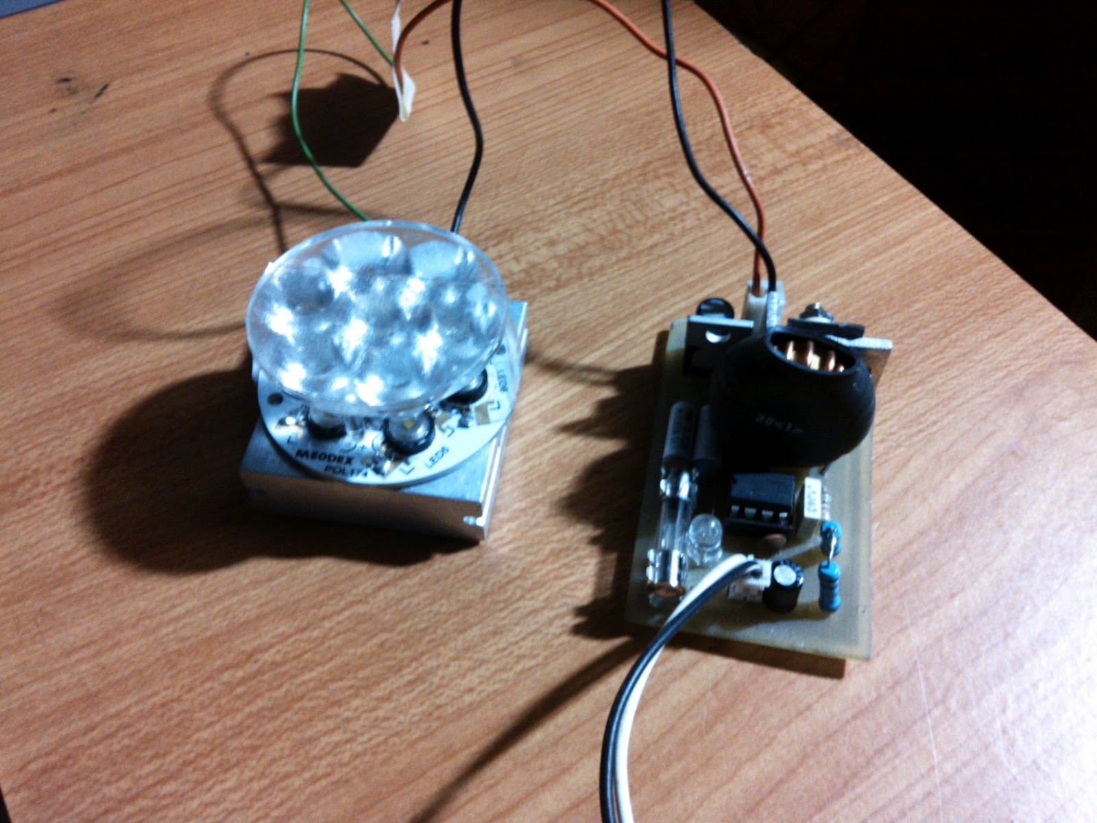


And its time to power up the led headlight to see how it went well. I used for this test 12 volts 1.5 ampere wall adapter.


Suzuki Emblem Logo Illuminated

Suzuki FL-125 suzuki logo illuminated.

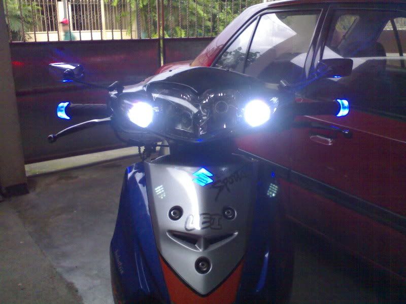
Illuminating those emblem logo on your motorcycles..is sometimes a head turner .featuring costumized suzuki logo illuminated version...This suzuki hayate is from a friend who dire to have his scooter something to look for..a simple head turner without altering its original look as is.
Side mirror signal light part 1
After some time of thinking how to make one..i finally decided to go for it and try to install one using my knowledge..At last, though still in a temporarily dry run to see how it paired..here it is
Read more »
its a KOSO immitation side mirror, with acrylic sheet placed inside and put leds to lit the sheet, just like my signalling BAR END. I wanted to create like those of a ford exped. van that has an arrow on the face of the mirror, but this immitation side mirror was not the type of mirror im looking for, those one way mirror like...Anyway, it still worth my patience.
THINGS needed to do the mods.
1. acrylic sheet size 3/4
2. metal polish
3. power tools, knife, mini drill,
4. sand papers, files,
5. patience

THINGS needed to do the mods.
1. acrylic sheet size 3/4
2. metal polish
3. power tools, knife, mini drill,
4. sand papers, files,
5. patience

High Power Leds

Power led is the new era of led lighting, both at home and automobile use. They come in a variety of it, from 1 watt up to 20 watts..being 20 watts made by china of course..
http://www.philipslumileds.com/
Lighting Company is the world's leading manufacturer of high-
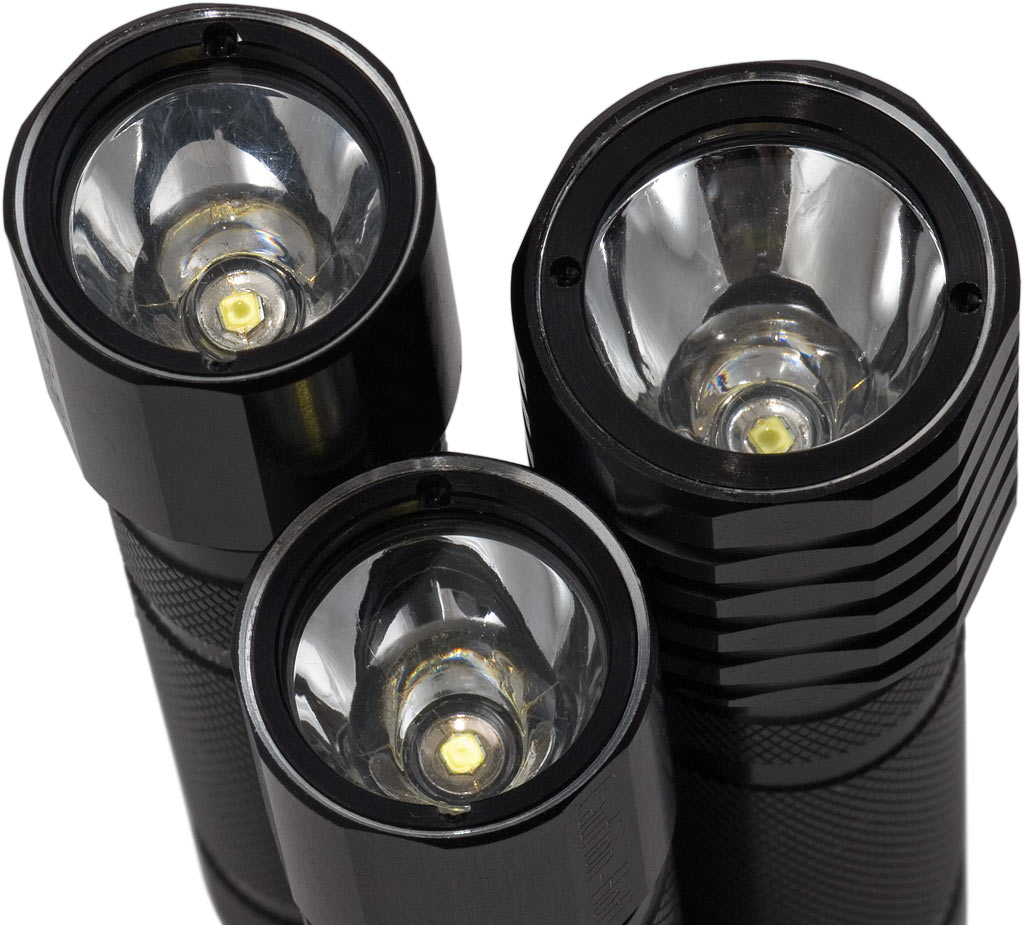
Such application of this leds are seen in flashlights as shown here. They are far better than those of maglite. They are also widely use as an alternative lighting solution to halogen on some mountain bikers worldwide due to their versatility. The only problem enthusiast who uses this kind of leds are the constant current driver itself..unlike those 5mm super bright leds, resistor or linear current regulator is enough for some simple applications, but for some who really want to gain the best of this leds, Constant current led drivers are there to the rescue.
Integrated TAIL/Brake, signal lights
Ever seen a ford expedition with just a full REAR red lights where a signal, tail and brake lights are done by those RED lights. They are called INTEGRATED rear lights and can be done on motorcycles too. Take a look at the video. This was the very first version of my diy works with my bike a long time ago, to where my signal lights tail lights and brake lights are compose with just an array of led at the rear.
Circuit:

I used this circuit posted led-brake-light This will be your TAIL/BRAKE light controller, it needs two of this for left and right led array assembly. to incorporate the SIGNAL lights on this circuit, we have to use two 12 volts miniature relay.
 two of this single pole single throw relay will be used to switched the negative line of the led array on the circuit above. The NC or normally closed pins will be used. Look at the modified schematic below.
 Cut the negative path of the led array from the driving mosfet and wired it to the normally closed pins of the relay so that when powered on the path of that negative pin of the array is still connected. And when you turn on the signal lights, the relay will be activated thus cutting the line of the led array producing a flashing effect on your integrated rear lights. This circuit by the way will be on all the time, that when you on the ignition switch, your tail light must be on so that the rear signal lights function during day time.
Part list:
D1-D2= 1n4007
ZD1= 15volts /1watt
ZD2= 9-14 volts / 500mw
L1=22uh
C1=15uf/35v
R1 / R4= 10k ohms
R2 = 1.3 ohms
R3 = 16.1 ohms
R5 = 2.2k ohms
VT1 = 2n3904
VT2 / VT3 = mtp3055e (mosfet)
for signal lights add on
RL1 / RL2 = 12 volts miniature pcb relay
Read more »
Circuit:

I used this circuit posted led-brake-light This will be your TAIL/BRAKE light controller, it needs two of this for left and right led array assembly. to incorporate the SIGNAL lights on this circuit, we have to use two 12 volts miniature relay.


Part list:
D1-D2= 1n4007
ZD1= 15volts /1watt
ZD2= 9-14 volts / 500mw
L1=22uh
C1=15uf/35v
R1 / R4= 10k ohms
R2 = 1.3 ohms
R3 = 16.1 ohms
R5 = 2.2k ohms
VT1 = 2n3904
VT2 / VT3 = mtp3055e (mosfet)
for signal lights add on
RL1 / RL2 = 12 volts miniature pcb relay
Inside E27 5 Watts Led


Super Park light
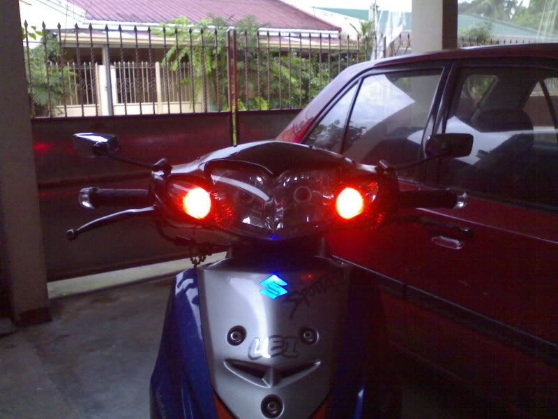
Been thinking of using 5mm leds as park light and signal lights as well, in replacement for filament type ones to conserve battery energy and minimize discharge activity to prolong its life..and came my first revision that uses the 5mm leds as park lights.
FIRST revision LED park lights.............still i used it for almost 2 years on my bike without no problem but then since i am an enthusiast and craving for more far ideas, i might think of..came my second revision. An alternating park and signal lights in action


Read more »
FIRST revision LED park lights.............still i used it for almost 2 years on my bike without no problem but then since i am an enthusiast and craving for more far ideas, i might think of..came my second revision. An alternating park and signal lights in action
Subscribe to:
Posts (Atom)