Showing posts with label DC-CDI. Show all posts
Showing posts with label DC-CDI. Show all posts
Tuesday, October 20, 2015
DC-CDI anatomy

This are some DC-CDI opened black boxes with its epoxy filled removed, and to understand and be familiar with each CDI being offered in the market, i may say some are almost identical and some are too complex to experiment with.
Here, a DC-cdi picture from whom an emailer sent to me and asking for some help. credit to you and thanks, I labeled this in order for others to understand which is which and what to look for.

DC-CDI ignition troubleshooting
Many small bikes of today and tomorrow are now using the DC-cdi technology, this is for reliability and mantaining good spark every now and then, but then at somehow and at somepoint, the system fails. How does it fails?
Firstly, we must understand how the system works from start to finish.
We'll now get into the ignition system itself. The outline simple enough. You start inside the left engine side cover, where two
PICKUPS
sit near the rotor and produce a pulse of electric current when the pistons near TDC (Top Dead Center) which is fed to the
sit near the rotor and produce a pulse of electric current when the pistons near TDC (Top Dead Center) which is fed to the
DC-CDI BOX
(Capacitive Discharge Ignition, variously called the "ignitor box", "brain box", etc.). This box has two basic functions. It adjusts the signal from the pickups based on engine speed to change the timing as needed, and a capacitor thats being charged by an internal HV generator in accordance with RPM switches an SCR dumping energy of the CAPACITOR to the primary winding of the
(Capacitive Discharge Ignition, variously called the "ignitor box", "brain box", etc.). This box has two basic functions. It adjusts the signal from the pickups based on engine speed to change the timing as needed, and a capacitor thats being charged by an internal HV generator in accordance with RPM switches an SCR dumping energy of the CAPACITOR to the primary winding of the
IGNITION COILS
so that the secondary winding is "induced" to spit out a high voltage shot to the
so that the secondary winding is "induced" to spit out a high voltage shot to the
SPARK PLUG WIRES and on to the
SPARK PLUG CAPS which in turn sends it to the
SPARK PLUGS
where all this voltage (maybe somewhere between 10kv to 40kv-that's thousands of volts) has enough pressure to make a small current jump the air gap between the electrodes at the bottom of the plug, thereby making a spark. This spark ignites the fuel mixture which, at that point is sitting all around the plug tip in a compressed state, ready to go BANG.
where all this voltage (maybe somewhere between 10kv to 40kv-that's thousands of volts) has enough pressure to make a small current jump the air gap between the electrodes at the bottom of the plug, thereby making a spark. This spark ignites the fuel mixture which, at that point is sitting all around the plug tip in a compressed state, ready to go BANG.
So that is basically what happens But things aren't quite this simple, and so we'll take each element and talk about it in more depth. We'll also note the problems we've run into, the tests that can be made, and the repairs/fixes we know about. Please understand I'm not a trained engineer just an electronics guy. My comments are based on what I've learned from reading, talking with people, and personal experience with the system.
Motorcycle Racing CDI Repair


After removing the entire coating of the bottom view of the board, just continue the removal now of the component side with many PATIENCE at hand.


There are many primary reason why it ended this way
1. Overvoltage of the supply
2. Temporary short at the ignition coil area. (output of the CDI to the ignition coil)
3. Wrong wiring connection
4. The least is factory defect...(found some solder residue that may causes the short path of each component in the high voltage section of this cdi)
Part II of this repair will be compose of the bench testing and actual video of it when back to life.
Kawasaki OEM DC-CDI
Ever wonder whats inside an OEM DC-CDI of kawasaki,
I got time to open up one just for all of my readers, with my step by step on how i did it without messing up the circuitry of the igniter. At first before i opened up this little black box. The Unit is covered with rubber epoxy and sometimes hardened epoxy to avoid malfunction from moist and vibration of the motorcycle.
 i tried not to mess up with the casing, unfortunately it didnt work for me, the plastic case is too brittle. slowly i chipped the casing with a diagonal cutter starting from the top cover. After hours doing the case thing. ,
The rubber epoxy will be exposed and time to strip it away so that the components of the board will be visible like this.
 I used bamboo stick, (do not use hard pointed objects on clearing this epoxy, we do not know where the components are and might get damage by it)..so better yet use stick. ( i did not use any solvent to strip this...i need the entire board intact and the semiconductors un damage...
Read more »
I got time to open up one just for all of my readers, with my step by step on how i did it without messing up the circuitry of the igniter. At first before i opened up this little black box. The Unit is covered with rubber epoxy and sometimes hardened epoxy to avoid malfunction from moist and vibration of the motorcycle.

The rubber epoxy will be exposed and time to strip it away so that the components of the board will be visible like this.

NEX 113cc

The new scooter of suzuki offers fuel efficiency with the addition of TPS (throttle position sensor) that signal the ignition when to enhance driveability of the machine.
Suzuki NEX 113cc was tag in Indonesia as the most Economical Scooter with a record of 79.6 km/liter on a 40-50 kph at sentul circuit.


Hopefully, suzuki philippines, launches the Fuel injected version so that it can compete with other brand.
Programmable DC-CDI test

(thanks to sir thierry of france with this, he inspired me more to fully understand everything.)
Photo shown is a homemade DC-CDI, got it from a site, more on that later.
Modifying DC-CDI

Looking at the picture (click to zoom), The MCU is actually made by freescale inc. a Motorola based MCU with a part number SC528524. The IC is actually a predefined package for the motorcycle manufacturer design, so getting the data out of it will be impossible, not unless you are one of the engineer and designer who actually built the black box.
The SC528524 is the heart of this CDI, it holds the data for generating the ignition map, the timing, the RPM limiter, the TPS switcher, the SCR gate trigger and the control of the High Voltage Converter. If and If only we have the datasheet of the MCU, perhaps we can be able to use the Rx and Tx pins to communicate it with a computer and proper software. But again, since it is a predefined MCU made only for them, reverse engineering with the current MCU is difficult.
 |
| Shogun DC-CDI MCU removed |
By tracing each section of the entire block box and redraw the schematic, all possible component of a good working ignition are all there, so by using any other MCU, an open source software may do the trick. How about using PIC Microcontroller made by Microchip, Yes there are lots of them all over the internet, just search them.
 |
| pic16f628A by microchip |
Photo shown is a very popular ignition made for remote controlled planes, It is an open source project by many people in a forum. Hardware and Firmware for the 16f628A microchip are all posted here...
1. www.transmic.net
2. www.electronics.gompy.net/

Digital DC-CDI schematic (full schematic diagram of shogun 125cc ignition controller)
 |
| Full schematic diagram of Suzuki Shogun DC-CDI |
1. Pulse Shaping Block
2. TPS Block
3. MCU block (heart of any digital CDI)
4. SCR/Capacitor block
5. High Voltage converter block (no alternator needed)
Pulse shaping and conditioner block

The circuit inside this block is responsible for the shaping and and clipping for the amplitude for the MCU to receive and access as the flywheel equipped with magnet passes through the pulser coil. Depending on the polarity of the coil, this circuit will receive that pulse every revolution whether positive or negative pulse. If the program of the MCU needs to receive only the negative pulse then this circuit will be responsible for making it a negative pulse if the polarity of the pulser is a positive output, and vice versa.
TPS block circuit

As the name implies. TPS corresponds to Throttle Positioning Sensor. This sense the throttle position by way of a switch fitted on the carburetor mainly, for improve acceleration purposes and or fuel efficiency delivery of the whole ignition front end. Not all CDI is equipped with such for a cdi can work with or without the TPS. But for an EFI system, TPS is a must. (but it will not covered with this article for the CDI being modified here is mainly for carbureted type ignition)
MCU block
The heart and source of all sensor and outputs the necessary command to the SCR, HV generator oscillator, and TPS input, as well as the pulser coil input. Depending on the firmware itself will make every cdi differs in performance and output. The stored ignition mapping will also tell the difference where the bike will pull hard at an RPM band. All CDI are created equal, only the ignition map differs. So why in the heck did they make such racing CDI if they are almost equal with the standard CDI. Theoretically, only the power on the certain RPM band will be moved, it will not grant you extra HP for a normal engine. If the engineers were able to get 50 reliable HP, they would have done it... but you can modify the distribution of the power. (Ex: more advance = more torque at a particular powerband) or remove the rev limiter that limits the probability of having above optimum performance.Concretely, to tune the advance curve according to the engine/exhaust/carburation/air filter and to get same extra HP, a real dynamometer will serve you as the basis of engine tuning, and not on the CDI alone.
SCR/Capacitor block

This is the area on when to charge and then discharge the capacitor the dump to the ignition coil. As the capacitor is charge by the HV converter, when the MCU sense the first pulse, it will then calculate everything via the ignition map stored on the MCU, either advance or retard, then trigger the scr gate at the right time..The engine will lose power when the CDI block fired the spark plug at the wrong timing due to wrong calculation and data of the MCU. so all in all, this block still rely on the MCU data.
High Voltage Converter Block
An important block for an ignition to be called DC-CDI. The circuit that is responsible of producing a large amount of voltage from 20kv up to 40kv, but of course depending on the design and topology used in this converter, the efficiency and reliability is important. Instead of having an external High voltage generator located in the generator side to which an AC-CDI use, DC-CDI do not have that kind of winding, instead it is placed inside the black box. An ocillator that is connected to the MCU SCR trigger output is needed to off and on the HV converter for charging and discharging the Capacitor and in sync with the SCR gate triggering to avoid the gate locking down during discharge. There are many design employed on a HV converter of dc-cdi, such as flyback converter, push pull converter, and the cheap low cost forward converter. In the circuitry above, they used the forward converter, only few components needed to have a cheap but reliable kind of converter for the CDI, although the efficiency is not that high in comparison with the flyback topology converter,
To be continued..for the placing of the pic16f628A and preliminary testing on the workbench before trying it on the bike,and communication with PC to update and change ignition map...Please be back thank you.
DC-CDI schematic (updated)
DC-CDI counterpart of AC-CDI is an ignition analog or digital that uses low voltage external power supply to work. the difference AC-CDI needs external High Voltage COIL no battery configuration whereas DC-CDI needs a battery without HV COIL.
Looking at the picture on the left, it is a complete schematic diagram of a dc-cdi. Its a 4-pin system, comprising pick-up input, battery +12 volts in, Gnd, and Ignition coil out pins. There is no High Voltage input pin like those of AC-CDI. If it will be differentiated with the AC-CDI here, you will notice theres a transformer diagram on this schematic.The circuit on the RED BOX comprises the internal High Voltage generator of a DC-CDI, where the 12 volts battery in will be converted to 200-400 volts depending on the design of the inverter. This design uses two transistor dc-ac converter with external on/off circuit to charge and discharge the capacitor BLUE BOX via SCR. the HV converter is controlled by the circuit on GRAY box, that as soon as the pulse conditioning circuit sense the pick-up coil will send triggering signal on both SCR and HV oscillator respectively to turn them on and off at the right time.
CDI or Capacitor Discharge Ignition, from the name itself, capacitor is very critical during its operation, must handle charge and discharge time as well as heat being generated by the whole circuit inside the block box, that is why manufacturer uses special capacitors specifically made for ignitions, and not just like those mylar capacitor found on some electronic circuits. They are rated 400 to 630 volts. ranging from .47uf up to 2.2uf. Value is also so critical in every applications and designs. In this circuit, they use 1uf / 400 volts with HV out of 200 volts will equals to 20 mj.
Read more »
 |
| DC-CDI schematic diagram |
Looking at the picture on the left, it is a complete schematic diagram of a dc-cdi. Its a 4-pin system, comprising pick-up input, battery +12 volts in, Gnd, and Ignition coil out pins. There is no High Voltage input pin like those of AC-CDI. If it will be differentiated with the AC-CDI here, you will notice theres a transformer diagram on this schematic.The circuit on the RED BOX comprises the internal High Voltage generator of a DC-CDI, where the 12 volts battery in will be converted to 200-400 volts depending on the design of the inverter. This design uses two transistor dc-ac converter with external on/off circuit to charge and discharge the capacitor BLUE BOX via SCR. the HV converter is controlled by the circuit on GRAY box, that as soon as the pulse conditioning circuit sense the pick-up coil will send triggering signal on both SCR and HV oscillator respectively to turn them on and off at the right time.
CDI or Capacitor Discharge Ignition, from the name itself, capacitor is very critical during its operation, must handle charge and discharge time as well as heat being generated by the whole circuit inside the block box, that is why manufacturer uses special capacitors specifically made for ignitions, and not just like those mylar capacitor found on some electronic circuits. They are rated 400 to 630 volts. ranging from .47uf up to 2.2uf. Value is also so critical in every applications and designs. In this circuit, they use 1uf / 400 volts with HV out of 200 volts will equals to 20 mj.
CDI Building Blocks
This article will cover how motorcycle capacitive discharge ignition works, its building blocks. How an AC-CDI can be made a DC-CDI, how the internal dc-dc converter of a dc-cdi affects the overall performance. First. we will cover the AC-cdi to which some scooters, moped, and some chinese made 2 wheels utilize. Looking at the picture, it covers the building block of an AC-CDI,
 it can easily be distinguished on any bike because they have the so called KILL switch to where it will disable the switching of the SCR or to cut the high voltage generator on supplying the capacitor to off the engine. Kill switch is a must for any ac-cdi circuit, and without it, the exciter or source coil will continue to rotate and supply high voltage to the capacitor.
AC-CDI can be made by enthusiast whether they are analog to digital, from simple to complex form, from fixed to a programmable to where you can adjust the ignition curve to meet your needs on racing or street driveability. Here we will not gather any information about racing CDI, for they are almost the same to what our bike is using, in short, they are only the modified version and sometimes, (this is not a fact but sometimes it is true) that they perform worse than those OEM fitted on our factory bikes, again but not all.
ANALOG AC-CDI
The simplest form of cdi which compose of discrete components, like resistor, capacitor, transistor, an scr and diodes.
 Here shown in the picture is an analog simple easy to build cdi. It has no advance function, the trigger of the scr is straight forward.
When pulses from the pick-up coil is sensed, it will produce voltage near but not more than 5volts. It will then be configure by D3 for positive pulse, and condition by the R2 and C2 for noise removal of the pick-up coil for SCR Q1 gate triggering.
Exciter or source coil will produce 60-120 volts, this depends on the power of the coil, is then converted by D1 to DC for C1 charging..
When the pulse arrived at SCR gate, it will be triggered and shunting the capacitor charge to ground and dumped it on the ignition coil, and because ignition coil is just a straight forward step up transformer, primary will then produce magnetic field transferring power to secondary winding and because of the ratio between the two windings about 1:100, secondary will produce a brief 20,000kv - 30,000kv then onto the ignition wire, then finally at the tip of the spark plug gap to produce an ARC.
DIGITAL AC-CDI
On the other hand, a digital AC-CDI form the name itself, compose of perhaps some digital ic like, microprocessors to where configuration of advance thru PC is probable. some uses micros like PIC, AVR, freescale, and the likes. example of this can be found from site like
http://sportdevices.com/ignition/ignition.htm
Comparing to the simple analog AC-CDI posted above, the triggering circuit before the gate of the SCR went from the microcontroller pic16f84A to which must be programmed according to the specification of your motorbike, I'll not tell you exactly how this circuit works, for all of the data are within their site.
This circuit can operate with or without battery but nonetheless, since microcontroller IC needs constant supply, it may be best to use a battery to avoid failure.
Again, there is the STOP engine button connected to the gate of the scr via ground to of course stop the engine.
The microcontroller do all the stuff for pulse conditioning, as well as retarding or advancing the ignition to make room for a configurable driveability of your motorbike.
AC-CDI , can be configured to work as a DC-CDI with the help of a high voltage dc-dc converter in replacement for the high voltage generator coil that supply the necessary voltage to charge the capacitor, and the more complex yet very effective dc-cdi comes to play.
DC-CDI
 Here a block diagram of this kind of ignition controller found nowadays on motorbike, the exciter coil, or source coil, or high voltage generator coil is omitted. but then a battery is in placed to power up the cdi. KILL switch is also omitted for once the power supply coming in from the battery is cut, there is no more power for the internal high voltage converter to use hence cutting of any means of charging the capacitor turning off the engine.
Only difference of the DC to AC type, here there will be a more complex circuit composed of the high voltage dc-dc converter that will act as the exciter coil or source coil. I will take this dc-cdi schematic for example.
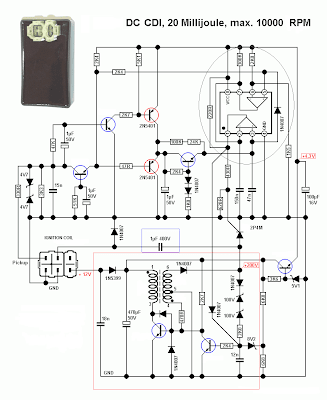
The circuit on the red block is the source of the high voltage and act as the source coil of an AC-CDI system. Its a free running oscillator, but unlike the exciter coil produces continuous voltage, HV converter must be turned off in relation to the triggering of the SCR switch. This is not to cause a shorted path when the SCR dumps the charge of the capacitor. They are timely tied together.
Depending on the frequency of the oscillator, this has a big effect on how fast it can charge the capacitor at higher revolution of the engine. This circuit sometimes limit the overall performance of any Capacitor Discharge ignition built. If they can be made to be more powerful then we may be able to have a higher performance cdi as what those so called racing cdi does. but we all know that having a powerful ignition output means more voltage is needed thus more current consumption on the battery. Other's often states that changing the charging capacitor to a higher value compensate for this trade off,
"As the size of the capacitor is increased, the output of the ignition also increases, however the oscillator must be made more powerful. Certain trade offs must be made in design for a particular application."
still without improving the High voltage converter circuit, ignition limitations is in place.
There are many variations of the HIGH VOLTAGE CONVERTER used on a dc-cdi, other uses the typical low cost forward converter type some uses the switching mode type with onboard IC like SG3525, UC3845, other use microcontroller to switch it on and off. There are too many variation of producing high voltage for this kind of ignition. The trade-off is actually the design, the size and the frequency of the oscillator to charge the capacitor at a faster time.
I am into currently modifying this OEM dc-cdi of my motorbike by replacing its onboard converter to a more powerful one posted here
suzuki-shogun-oem-dc-cdi
and will try to use this kind of high voltage converter schematic

I am into modifying for a smaller pcb for this so that i can put it right on top of the original dc-cdi board. This high voltage can be configured by modifying the feedback control resistors R2 and R3.
Read more »

AC-CDI can be made by enthusiast whether they are analog to digital, from simple to complex form, from fixed to a programmable to where you can adjust the ignition curve to meet your needs on racing or street driveability. Here we will not gather any information about racing CDI, for they are almost the same to what our bike is using, in short, they are only the modified version and sometimes, (this is not a fact but sometimes it is true) that they perform worse than those OEM fitted on our factory bikes, again but not all.
ANALOG AC-CDI
The simplest form of cdi which compose of discrete components, like resistor, capacitor, transistor, an scr and diodes.

When pulses from the pick-up coil is sensed, it will produce voltage near but not more than 5volts. It will then be configure by D3 for positive pulse, and condition by the R2 and C2 for noise removal of the pick-up coil for SCR Q1 gate triggering.
Exciter or source coil will produce 60-120 volts, this depends on the power of the coil, is then converted by D1 to DC for C1 charging..
When the pulse arrived at SCR gate, it will be triggered and shunting the capacitor charge to ground and dumped it on the ignition coil, and because ignition coil is just a straight forward step up transformer, primary will then produce magnetic field transferring power to secondary winding and because of the ratio between the two windings about 1:100, secondary will produce a brief 20,000kv - 30,000kv then onto the ignition wire, then finally at the tip of the spark plug gap to produce an ARC.
DIGITAL AC-CDI
On the other hand, a digital AC-CDI form the name itself, compose of perhaps some digital ic like, microprocessors to where configuration of advance thru PC is probable. some uses micros like PIC, AVR, freescale, and the likes. example of this can be found from site like
http://sportdevices.com/ignition/ignition.htm
 |
| PICTURE property of SPORTDEVICES.COM |
This circuit can operate with or without battery but nonetheless, since microcontroller IC needs constant supply, it may be best to use a battery to avoid failure.
Again, there is the STOP engine button connected to the gate of the scr via ground to of course stop the engine.
The microcontroller do all the stuff for pulse conditioning, as well as retarding or advancing the ignition to make room for a configurable driveability of your motorbike.
AC-CDI , can be configured to work as a DC-CDI with the help of a high voltage dc-dc converter in replacement for the high voltage generator coil that supply the necessary voltage to charge the capacitor, and the more complex yet very effective dc-cdi comes to play.
DC-CDI

Only difference of the DC to AC type, here there will be a more complex circuit composed of the high voltage dc-dc converter that will act as the exciter coil or source coil. I will take this dc-cdi schematic for example.

The circuit on the red block is the source of the high voltage and act as the source coil of an AC-CDI system. Its a free running oscillator, but unlike the exciter coil produces continuous voltage, HV converter must be turned off in relation to the triggering of the SCR switch. This is not to cause a shorted path when the SCR dumps the charge of the capacitor. They are timely tied together.
Depending on the frequency of the oscillator, this has a big effect on how fast it can charge the capacitor at higher revolution of the engine. This circuit sometimes limit the overall performance of any Capacitor Discharge ignition built. If they can be made to be more powerful then we may be able to have a higher performance cdi as what those so called racing cdi does. but we all know that having a powerful ignition output means more voltage is needed thus more current consumption on the battery. Other's often states that changing the charging capacitor to a higher value compensate for this trade off,
"As the size of the capacitor is increased, the output of the ignition also increases, however the oscillator must be made more powerful. Certain trade offs must be made in design for a particular application."
still without improving the High voltage converter circuit, ignition limitations is in place.
There are many variations of the HIGH VOLTAGE CONVERTER used on a dc-cdi, other uses the typical low cost forward converter type some uses the switching mode type with onboard IC like SG3525, UC3845, other use microcontroller to switch it on and off. There are too many variation of producing high voltage for this kind of ignition. The trade-off is actually the design, the size and the frequency of the oscillator to charge the capacitor at a faster time.
I am into currently modifying this OEM dc-cdi of my motorbike by replacing its onboard converter to a more powerful one posted here
suzuki-shogun-oem-dc-cdi
and will try to use this kind of high voltage converter schematic

I am into modifying for a smaller pcb for this so that i can put it right on top of the original dc-cdi board. This high voltage can be configured by modifying the feedback control resistors R2 and R3.
Shogun DC-CDI schematic

Digital DC-CDI by the way uses microprocessor on the pulse shaping circuit to maintain integrity and reliability of giving out right timing all the time when the spark plug will fire the combustible material inside the combustion, it is also to where the ignition map of the engine is stored for accurate timing. Many OEM uses MCU specific for their design and no available datasheet for us to understand it fully. This OEM upon analyzing the entire board has an Rx, Tx, and ground port, and if only i have the datasheet of the IC, perhaps we can be able to extract the data and dump it to a computer for further enhancement.
Testing Motorcycle CDI Ignition Coil

Primary winding compose of few turns thus resistance reading will show milliohms reading and almost zero when using ordinary DVM, thus inductance may be a better choice for an instrument to test it, while as the secondary compose of a hundred turns, it is capable of resistance test.
here are the variation of reading of those three mentioned CDI coil above


I did this test to be able to determine how it will affect my ignition before i tried to test it on board my motorcycle with the exception of my OEM. Yes they will all work since they are made for a CD ignition. and this inductance will primarily affect the transfer of energy towards the secondary winding of the coil.
For the secondary winding basic test, i use the resistance check, for my homemade inductance tester can only reach the 1 mh range.


Higher resistance reading of the secondary means more number of turns and may transform it to a higher voltage output when the primary is being switched by the ignition controller, but then the primary winding also has an adverse effect on the secondary winding. Only by using HIGH voltage tester, we can assure of the reading, but because ignition coil are HIGHLY shield by epoxy resin, we cannot determine if the theory is in fact true that the more number of turns and higher resistance reading will produce more hotter spark.
Soon i will try to make an IGNITION COIL tester to see how the spark is generated by this three outside the combustion..
but then what we will see outside will differ if its inside due the pressure of the combustion. as of now resistance and inductance test is highly recommended for those who wants to try out different CDI coil available.
I am using by the way the china made coil, rather than my SHOGUN OEM, for a change. :-)
Subscribe to:
Posts (Atom)