Showing posts with label ignition coil. Show all posts
Showing posts with label ignition coil. Show all posts
Tuesday, October 20, 2015
Understanding Motorcycle Switches
Ignition performance (trick)
Understanding Switches of your motorcycle
We all know the characteristic of every switch out there that turns on and turns off the supply of any electronic equipment. They operate in such a way that the two contacts just slide with each other, and therefore prone to corrosion, moisture and degration. This in turns lower the efficiency since the contact is not 100 percent in contact with one another. More often, if the switch handle current more than their rated characteristics, then it heats up building more corrosion and blackening, producing more contact problems. A slight increase on their resistance, produces problems to current flow.
Now let us examine all possible switches there is on a motorcycle. What are they and what they are switching?
let us start, (add more on comments if i missed something)
IGNITION SWITCH
HORN switch
TURN SIGNAL switch
BREAK LIGHT switch (front and rear)
HEADLIGHT switch
HEADLIGHT BEAM switch (HI and LOW)
Now we will analyze each and one of them, i'll start from the bottom.
Read more »
Understanding Switches of your motorcycle
We all know the characteristic of every switch out there that turns on and turns off the supply of any electronic equipment. They operate in such a way that the two contacts just slide with each other, and therefore prone to corrosion, moisture and degration. This in turns lower the efficiency since the contact is not 100 percent in contact with one another. More often, if the switch handle current more than their rated characteristics, then it heats up building more corrosion and blackening, producing more contact problems. A slight increase on their resistance, produces problems to current flow.
Now let us examine all possible switches there is on a motorcycle. What are they and what they are switching?
let us start, (add more on comments if i missed something)
IGNITION SWITCH
HORN switch
TURN SIGNAL switch
BREAK LIGHT switch (front and rear)
HEADLIGHT switch
HEADLIGHT BEAM switch (HI and LOW)
Now we will analyze each and one of them, i'll start from the bottom.
Ignition Wire Ground Strap

I have been reading all through the net about ground strapping the entire ignition wire in order for the whole system have its own grounding strap instead of relying on the engine chassis ground to i think produce a consistent END part of the ignition to make it more reliable. So why not give a try.
Here what we are going to do is, Adding a direct ground connection on the ignition coil ground down to the cylinder head to where the spark plug is bolted and rely on the engine chassis ground. Materials needed are the following.

Ground strap---this can be found on some computer cables, like the VGA cable, Parallel port cable, etc etc.
We need to remove the other wires inside this ground strap, so that it can be inserted on the ignition wire.


To protect the ground strap from dust, water and any forms of road debris, we need something to hold of also in its place and SHRINK tubing is i think the best for this job. It can be bought at any electronic supply parts nationwide.


Many people will try to ask,
1.What will be GAINED on doing this kind of MODIFICATION or trick?
ANS: I myself was amazed of doing this kind of mod from a site i recently saw, and logically thinking, why not, thinking outide the box, why the ignition end do not have a proper ground strap and just rely on the engine chassis, and making this mod really make sense that instead of the usual way, why not directly connect such ground as well as ground strapping the entire ignition wire to block any unwanted interference that might affect ignition.
TEST your bike after this mod, if you felt your throttle much crispier than before without this modification, there its a success, for thats why i felt.
2. Why not just put a wire and bolt it like the way you did instead of adding it on the ignition wire?
ANS: It can be used instead of following this kind of modification, what i intend to do was make it clean, and that's how it came out using ground strap, perhaps they'll both the same trick, JUST being clean though.
CDI Building Blocks
This article will cover how motorcycle capacitive discharge ignition works, its building blocks. How an AC-CDI can be made a DC-CDI, how the internal dc-dc converter of a dc-cdi affects the overall performance. First. we will cover the AC-cdi to which some scooters, moped, and some chinese made 2 wheels utilize. Looking at the picture, it covers the building block of an AC-CDI,
 it can easily be distinguished on any bike because they have the so called KILL switch to where it will disable the switching of the SCR or to cut the high voltage generator on supplying the capacitor to off the engine. Kill switch is a must for any ac-cdi circuit, and without it, the exciter or source coil will continue to rotate and supply high voltage to the capacitor.
AC-CDI can be made by enthusiast whether they are analog to digital, from simple to complex form, from fixed to a programmable to where you can adjust the ignition curve to meet your needs on racing or street driveability. Here we will not gather any information about racing CDI, for they are almost the same to what our bike is using, in short, they are only the modified version and sometimes, (this is not a fact but sometimes it is true) that they perform worse than those OEM fitted on our factory bikes, again but not all.
ANALOG AC-CDI
The simplest form of cdi which compose of discrete components, like resistor, capacitor, transistor, an scr and diodes.
 Here shown in the picture is an analog simple easy to build cdi. It has no advance function, the trigger of the scr is straight forward.
When pulses from the pick-up coil is sensed, it will produce voltage near but not more than 5volts. It will then be configure by D3 for positive pulse, and condition by the R2 and C2 for noise removal of the pick-up coil for SCR Q1 gate triggering.
Exciter or source coil will produce 60-120 volts, this depends on the power of the coil, is then converted by D1 to DC for C1 charging..
When the pulse arrived at SCR gate, it will be triggered and shunting the capacitor charge to ground and dumped it on the ignition coil, and because ignition coil is just a straight forward step up transformer, primary will then produce magnetic field transferring power to secondary winding and because of the ratio between the two windings about 1:100, secondary will produce a brief 20,000kv - 30,000kv then onto the ignition wire, then finally at the tip of the spark plug gap to produce an ARC.
DIGITAL AC-CDI
On the other hand, a digital AC-CDI form the name itself, compose of perhaps some digital ic like, microprocessors to where configuration of advance thru PC is probable. some uses micros like PIC, AVR, freescale, and the likes. example of this can be found from site like
http://sportdevices.com/ignition/ignition.htm
Comparing to the simple analog AC-CDI posted above, the triggering circuit before the gate of the SCR went from the microcontroller pic16f84A to which must be programmed according to the specification of your motorbike, I'll not tell you exactly how this circuit works, for all of the data are within their site.
This circuit can operate with or without battery but nonetheless, since microcontroller IC needs constant supply, it may be best to use a battery to avoid failure.
Again, there is the STOP engine button connected to the gate of the scr via ground to of course stop the engine.
The microcontroller do all the stuff for pulse conditioning, as well as retarding or advancing the ignition to make room for a configurable driveability of your motorbike.
AC-CDI , can be configured to work as a DC-CDI with the help of a high voltage dc-dc converter in replacement for the high voltage generator coil that supply the necessary voltage to charge the capacitor, and the more complex yet very effective dc-cdi comes to play.
DC-CDI
 Here a block diagram of this kind of ignition controller found nowadays on motorbike, the exciter coil, or source coil, or high voltage generator coil is omitted. but then a battery is in placed to power up the cdi. KILL switch is also omitted for once the power supply coming in from the battery is cut, there is no more power for the internal high voltage converter to use hence cutting of any means of charging the capacitor turning off the engine.
Only difference of the DC to AC type, here there will be a more complex circuit composed of the high voltage dc-dc converter that will act as the exciter coil or source coil. I will take this dc-cdi schematic for example.
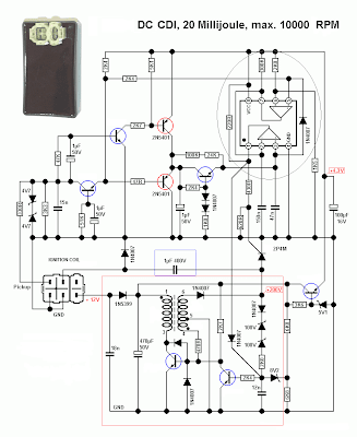
The circuit on the red block is the source of the high voltage and act as the source coil of an AC-CDI system. Its a free running oscillator, but unlike the exciter coil produces continuous voltage, HV converter must be turned off in relation to the triggering of the SCR switch. This is not to cause a shorted path when the SCR dumps the charge of the capacitor. They are timely tied together.
Depending on the frequency of the oscillator, this has a big effect on how fast it can charge the capacitor at higher revolution of the engine. This circuit sometimes limit the overall performance of any Capacitor Discharge ignition built. If they can be made to be more powerful then we may be able to have a higher performance cdi as what those so called racing cdi does. but we all know that having a powerful ignition output means more voltage is needed thus more current consumption on the battery. Other's often states that changing the charging capacitor to a higher value compensate for this trade off,
"As the size of the capacitor is increased, the output of the ignition also increases, however the oscillator must be made more powerful. Certain trade offs must be made in design for a particular application."
still without improving the High voltage converter circuit, ignition limitations is in place.
There are many variations of the HIGH VOLTAGE CONVERTER used on a dc-cdi, other uses the typical low cost forward converter type some uses the switching mode type with onboard IC like SG3525, UC3845, other use microcontroller to switch it on and off. There are too many variation of producing high voltage for this kind of ignition. The trade-off is actually the design, the size and the frequency of the oscillator to charge the capacitor at a faster time.
I am into currently modifying this OEM dc-cdi of my motorbike by replacing its onboard converter to a more powerful one posted here
suzuki-shogun-oem-dc-cdi
and will try to use this kind of high voltage converter schematic

I am into modifying for a smaller pcb for this so that i can put it right on top of the original dc-cdi board. This high voltage can be configured by modifying the feedback control resistors R2 and R3.
Read more »

AC-CDI can be made by enthusiast whether they are analog to digital, from simple to complex form, from fixed to a programmable to where you can adjust the ignition curve to meet your needs on racing or street driveability. Here we will not gather any information about racing CDI, for they are almost the same to what our bike is using, in short, they are only the modified version and sometimes, (this is not a fact but sometimes it is true) that they perform worse than those OEM fitted on our factory bikes, again but not all.
ANALOG AC-CDI
The simplest form of cdi which compose of discrete components, like resistor, capacitor, transistor, an scr and diodes.

When pulses from the pick-up coil is sensed, it will produce voltage near but not more than 5volts. It will then be configure by D3 for positive pulse, and condition by the R2 and C2 for noise removal of the pick-up coil for SCR Q1 gate triggering.
Exciter or source coil will produce 60-120 volts, this depends on the power of the coil, is then converted by D1 to DC for C1 charging..
When the pulse arrived at SCR gate, it will be triggered and shunting the capacitor charge to ground and dumped it on the ignition coil, and because ignition coil is just a straight forward step up transformer, primary will then produce magnetic field transferring power to secondary winding and because of the ratio between the two windings about 1:100, secondary will produce a brief 20,000kv - 30,000kv then onto the ignition wire, then finally at the tip of the spark plug gap to produce an ARC.
DIGITAL AC-CDI
On the other hand, a digital AC-CDI form the name itself, compose of perhaps some digital ic like, microprocessors to where configuration of advance thru PC is probable. some uses micros like PIC, AVR, freescale, and the likes. example of this can be found from site like
http://sportdevices.com/ignition/ignition.htm
 |
| PICTURE property of SPORTDEVICES.COM |
This circuit can operate with or without battery but nonetheless, since microcontroller IC needs constant supply, it may be best to use a battery to avoid failure.
Again, there is the STOP engine button connected to the gate of the scr via ground to of course stop the engine.
The microcontroller do all the stuff for pulse conditioning, as well as retarding or advancing the ignition to make room for a configurable driveability of your motorbike.
AC-CDI , can be configured to work as a DC-CDI with the help of a high voltage dc-dc converter in replacement for the high voltage generator coil that supply the necessary voltage to charge the capacitor, and the more complex yet very effective dc-cdi comes to play.
DC-CDI

Only difference of the DC to AC type, here there will be a more complex circuit composed of the high voltage dc-dc converter that will act as the exciter coil or source coil. I will take this dc-cdi schematic for example.

The circuit on the red block is the source of the high voltage and act as the source coil of an AC-CDI system. Its a free running oscillator, but unlike the exciter coil produces continuous voltage, HV converter must be turned off in relation to the triggering of the SCR switch. This is not to cause a shorted path when the SCR dumps the charge of the capacitor. They are timely tied together.
Depending on the frequency of the oscillator, this has a big effect on how fast it can charge the capacitor at higher revolution of the engine. This circuit sometimes limit the overall performance of any Capacitor Discharge ignition built. If they can be made to be more powerful then we may be able to have a higher performance cdi as what those so called racing cdi does. but we all know that having a powerful ignition output means more voltage is needed thus more current consumption on the battery. Other's often states that changing the charging capacitor to a higher value compensate for this trade off,
"As the size of the capacitor is increased, the output of the ignition also increases, however the oscillator must be made more powerful. Certain trade offs must be made in design for a particular application."
still without improving the High voltage converter circuit, ignition limitations is in place.
There are many variations of the HIGH VOLTAGE CONVERTER used on a dc-cdi, other uses the typical low cost forward converter type some uses the switching mode type with onboard IC like SG3525, UC3845, other use microcontroller to switch it on and off. There are too many variation of producing high voltage for this kind of ignition. The trade-off is actually the design, the size and the frequency of the oscillator to charge the capacitor at a faster time.
I am into currently modifying this OEM dc-cdi of my motorbike by replacing its onboard converter to a more powerful one posted here
suzuki-shogun-oem-dc-cdi
and will try to use this kind of high voltage converter schematic

I am into modifying for a smaller pcb for this so that i can put it right on top of the original dc-cdi board. This high voltage can be configured by modifying the feedback control resistors R2 and R3.
Testing Motorcycle CDI Ignition Coil

Primary winding compose of few turns thus resistance reading will show milliohms reading and almost zero when using ordinary DVM, thus inductance may be a better choice for an instrument to test it, while as the secondary compose of a hundred turns, it is capable of resistance test.
here are the variation of reading of those three mentioned CDI coil above


I did this test to be able to determine how it will affect my ignition before i tried to test it on board my motorcycle with the exception of my OEM. Yes they will all work since they are made for a CD ignition. and this inductance will primarily affect the transfer of energy towards the secondary winding of the coil.
For the secondary winding basic test, i use the resistance check, for my homemade inductance tester can only reach the 1 mh range.


Higher resistance reading of the secondary means more number of turns and may transform it to a higher voltage output when the primary is being switched by the ignition controller, but then the primary winding also has an adverse effect on the secondary winding. Only by using HIGH voltage tester, we can assure of the reading, but because ignition coil are HIGHLY shield by epoxy resin, we cannot determine if the theory is in fact true that the more number of turns and higher resistance reading will produce more hotter spark.
Soon i will try to make an IGNITION COIL tester to see how the spark is generated by this three outside the combustion..
but then what we will see outside will differ if its inside due the pressure of the combustion. as of now resistance and inductance test is highly recommended for those who wants to try out different CDI coil available.
I am using by the way the china made coil, rather than my SHOGUN OEM, for a change. :-)
Subscribe to:
Posts (Atom)