Showing posts with label AC-CDI. Show all posts
Showing posts with label AC-CDI. Show all posts
Tuesday, October 20, 2015
CRM250 MD24 CDI no spark problem

The problem was the CDI which is costly refuses to give a spark. All external component that directs to the ignition controller are all good and thus only the cdi was the suspect.The motorcycle was on a restoration process, and only the ignition was the problem. I had asked his permission to post all the photos here for others who has the same problem that may help you just in case.

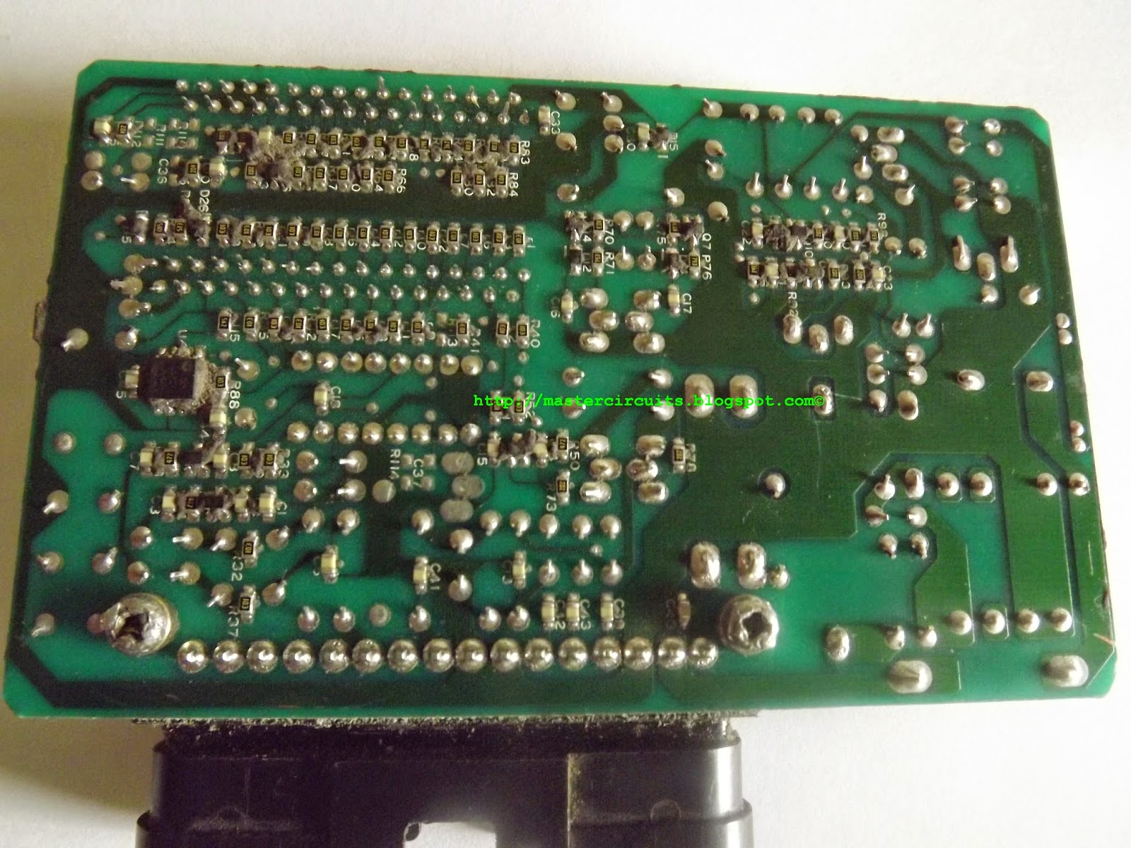
Of course, in order for you to do so is stripped all of the epoxy resin that covers the whole black box to expose the board which is very tricky and extra care and more patience is needed. All components must be intact to the board or else it will be much harder to determine what component had failed. Servicing a defective Ignition Controller is difficult and have to isolate each and one block from one another.
Through e-mail, he sent me all the photos needed as shown.
 |
| Fig. 1 |
 |
| Fig. 2 |
 |
| Fig. 3 |
 |
| Fig. 4 |
 |
| Fig. 5 |
 |
| Fig. 6 |
 |
| Fig. 7 |
By the way, the CDI of CRM250 MD24 is an AC-CDI type, it has an external high voltage exciter coil that charges the capacitor as the engine is turn. This means that the higher the engine rpm, the higher the voltage can be measured at the charging capacitor.
Moving on finding the culprit of the no spark symptoms of this cdi. Test was done trying to find why it refuses to spark at the tip of the spark plug. Figure 6 shows the voltage reading from turning the engine indicates that there is a voltage at the anode pin of the thyristor. This means that the high voltage of the generator is getting inside, indicating a healthy High voltage generator. One pin of the charging capacitor is connected to that cathode pin of the switching thyristor (SCR), hence there will be voltage, but there will be no vltage at the other pin if your reference is ground, since the charge can only be dumped to the ignition coils primary winding, which act as the load when the SCR is triggered by the MCU. If all is good, the charge will then be dumped causing a momentary magnetic field to that winding and transferred it to the secondary winding in a x10 ratio which is enough to create spark at the tip of the spark plug.
And that is where the problem exist. It does not create any spark. Hence, with the existence of voltage across the capacitor.(by the way to see the voltage is being kept by the capacitor before the dump, put the voltage meter probe across the two pins on the charging capacitor. Voltage will remain there up until the SCR is triggered.)
So before the capacitor, the circuit is generally good. but then the output towards the ignition coil output is not. Generally, If you look at all CDI schematic posted all over the internet, there is still a major component after the pin of the charging capacitor..(did u notice it)
 |
| Fig 8 |
That DIODE in regards to the CRM250 MD24 photo,was traced and looking at Fig. 5. designated as D16..
And guess what, It is actually shorted. If that is already shorted then the path of the charging capacitor is nearly directs to ground and no charge will be directed to the ignition coil..
In other words, when the damping diode is already shorted, the charge will no longer flow to the ignition coil, and the system is stopped. Seems odd..that is how it works.
Many will think how the damping diode actually get blown. SIMPLE
if the ignition coil is removed from the circuit and tried to turn the engine without it. The diode will then get the ACTUAL charged of the capacitor and dumps it to ground. It is like shorting the capacitor so that it will discharged the content via the SCR. Eitherway both the SCR and the damping diode will be force to short out. and one of them will get blown, and unfortunately, D16 gets the short condition first seizing the entire circuit from functioning.
So as to state if it is good to disconnect the ignition coil to the output of the cdi when you try to turn the engine..
the answer: NO so always make sure the ignition coil is connected to the cdi. Avoid cranking the engine without any ignition coil connected, Remember, It is easier to fix IGNITION COIL related problems that CDI one, since the later is an external part of the cdi. Internal part of the ignition controller is not exposed and CDI replacement will be costly.
All credit of the photos goes to Mr. David Cooper of UK. Thank you very much, Cheers mate!
DC-CDI ignition troubleshooting
Many small bikes of today and tomorrow are now using the DC-cdi technology, this is for reliability and mantaining good spark every now and then, but then at somehow and at somepoint, the system fails. How does it fails?
Firstly, we must understand how the system works from start to finish.
We'll now get into the ignition system itself. The outline simple enough. You start inside the left engine side cover, where two
PICKUPS
sit near the rotor and produce a pulse of electric current when the pistons near TDC (Top Dead Center) which is fed to the
sit near the rotor and produce a pulse of electric current when the pistons near TDC (Top Dead Center) which is fed to the
DC-CDI BOX
(Capacitive Discharge Ignition, variously called the "ignitor box", "brain box", etc.). This box has two basic functions. It adjusts the signal from the pickups based on engine speed to change the timing as needed, and a capacitor thats being charged by an internal HV generator in accordance with RPM switches an SCR dumping energy of the CAPACITOR to the primary winding of the
(Capacitive Discharge Ignition, variously called the "ignitor box", "brain box", etc.). This box has two basic functions. It adjusts the signal from the pickups based on engine speed to change the timing as needed, and a capacitor thats being charged by an internal HV generator in accordance with RPM switches an SCR dumping energy of the CAPACITOR to the primary winding of the
IGNITION COILS
so that the secondary winding is "induced" to spit out a high voltage shot to the
so that the secondary winding is "induced" to spit out a high voltage shot to the
SPARK PLUG WIRES and on to the
SPARK PLUG CAPS which in turn sends it to the
SPARK PLUGS
where all this voltage (maybe somewhere between 10kv to 40kv-that's thousands of volts) has enough pressure to make a small current jump the air gap between the electrodes at the bottom of the plug, thereby making a spark. This spark ignites the fuel mixture which, at that point is sitting all around the plug tip in a compressed state, ready to go BANG.
where all this voltage (maybe somewhere between 10kv to 40kv-that's thousands of volts) has enough pressure to make a small current jump the air gap between the electrodes at the bottom of the plug, thereby making a spark. This spark ignites the fuel mixture which, at that point is sitting all around the plug tip in a compressed state, ready to go BANG.
So that is basically what happens But things aren't quite this simple, and so we'll take each element and talk about it in more depth. We'll also note the problems we've run into, the tests that can be made, and the repairs/fixes we know about. Please understand I'm not a trained engineer just an electronics guy. My comments are based on what I've learned from reading, talking with people, and personal experience with the system.
5 pin AC-CDI

Yamaha DT125 CDI
This is the diagram of a china replica CDI (capacitive discharge ignition) of Yamaha DT125 2 stroke machine. The circuit can be used on other existing AC-cdi motorcycle, as long as there is a high voltage generator on the stator.

Read more »

HTML Comment Box is loading comments...
AC-CDI
Inside an AC-CDI of a GY6 50cc-125cc engine. An AC-CDI is a type of ignition wherein it can be operated without a battery installed on a bike but needing a HIGH VOLTAGE GENERATOR that will charge the capacitor inside the cdi to discharge tthrough your ignition coil producing spark at the spark plug unlike, dc-cd wherein no HV generator is necessary for they have a built in converter inside.
The circuit below is from a gy6 based engine. it incorporate a pulse shaping circuit, unlike the cdi of yamaha DT125 posted here Yamaha DT125 cdi.

for more ac cdi circuits and schematic diagram click here
More Ac-cdi schematic for you...
Read more »
The circuit below is from a gy6 based engine. it incorporate a pulse shaping circuit, unlike the cdi of yamaha DT125 posted here Yamaha DT125 cdi.

for more ac cdi circuits and schematic diagram click here
More Ac-cdi schematic for you...
Subscribe to:
Posts (Atom)